SUNFLOWER DEHULLER
Horizontal sunflower impact dehuller NRH-4 of continuous action are designed for dehulling of oilseeds at the enterprises of fat and oil industry.
The machine is produced in accordance with third category of GOST-15150, climate version “U” for internal market and export to temperate countries. However, dehullers have to work reliably in operating regimes at a temperature from 10 (°?) degrees below zero to 40 (°?) degrees above zero, relative moisture 80% with average annual temperature of 15 (°?) degrees above zero, atmospheric pressure from 650 to 800 mm Hg (86,6÷106,7 kPa). Single-, double-, triple-shift mode.
| Parameter | Value |
| Capacity (depending on processing intensity), tons per day | 50 |
| Speed, rpm with frequency-regulated drive without frequency-regulated drive: with engine pulley Ø 125 Ø 133,9 Ø140,6 | 560-630 560 600 630 |
| Rotor diameter, mm | 800 |
| Rotor width, mm | 980 |
| Rated capacity, kW | 7,5 |
| Air consumption for aspiration, m3/h | 610 |
| Specified service life prior to capital repair, years min. | 5 |
| Specified total service life | 13 |
| Overall dimensions, mm: length width height | 1735 1315 1710 |
| Weight, kg | 1450 |
| Content, %: | ||
| unhulled seeds | 10,98 | 12,68 |
| partially hulled seeds | 8,84 | 4,82 |
| kernel | 40,48 | 43,87 |
| husk/td> | 12,50 | 18,41 |
| half kernels (chop) | 11,07 | 8,49 |
| Oil containing dust, % | 16,13 | 11,73 |
Structure and Functioning
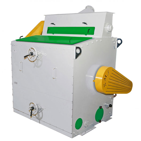
The machine (pic.1) consists of body frame 1 (where bearing cartridges are installed and hold rotor 2), deck plate 3 and deck plate holder 4, lower 5 and upper 6 mechanisms for regulation of clearance between rotor and deck plate, feeder 7, adjustable curtain 8, drive 9, retaining walls 10 and 11, aspiration channel 12 (as machine doesn’t have its own fan, it is connected to the central aspiration pipe-line). Rotor 2 is rotated by V-belt transmission due to actuating motor, which is installed on the back wall 21 of the machine.
Feeding roller 14 is rotated by V-belt transmission from rotor 2 through countershaft and placed in the feeder 7. Due to the throttle 16 and feeding roller 14, product is distributed over the entire width of the feeder and supplied to the feeder 17 tray, which serves for grain supply to the functional area between rotor and deck plate (dehulling chamber). In the chamber dehulling of seeds is occurred by numerous hammers impacts and seeds removal to the seamy surface of deck plate.
After dehulling, kernels and hulls are transferred to the outlet of the machine by the curtain. Intensity of seeds dehulling in the chamber is regulated by the clearance adjustment between deck plate and hammers.
To Achieve Designed Capacity, Proceed As Follows:
1. Normal circumferential speed of the beater must be installed at the level 25 m/sec. that corresponds 600 rpm, seeds distribution over the entire width of the drum can be achieved by the regulation of throttle in the feeder.
2. Distance between hammers and seamy surface of deck plate must be adjusted in accordance with grain type and its moisture content.
Reduction of this distance and increase of circumferential speed improves seeds dehulling, but at the same time increases chop (half kernels) formation process and dust content.
Adjusted position of deck plate seamy surface towards beater and selected circumferential speed must provide the capacity specified in product certificate.
3. The flow of transferred seeds must be adjusted by regulation of slot between valve and ribbed roller.
4. Set the normal air mode in dehulling chamber.
Speed of air flows must be regulated to avoid seeds transfer to light tailings during intensive aspiration.
The machine operates in accordance with following technological process:
Product, which must be dehulled, enters to the inlet nozzle and through feeder is transferred to receiving tray and further to functional area between rotor and deck plate. After dehulling between deck plate and rotor, product is removed from the machine through outlet port located in the floor. The air flow moves against dehulling seeds and carries over light particles and hulls through aspiration channel. Probe sampling is carried out through special access doors 22.
To ensure the normal machine operation gate valve or throttle must be installed before inlet nozzle. The magnetic protection also must be obligatory installed.